

In HeatAlgo's radiant floor heating module, you work on the floor plan of one story at a time: you draw heated sections, choose the tubing layout and connect each loop to the manifold. The app recalculates loop lengths, floor output and flows after every change. To check the balance, you need each room's heat loss - from the heat loss calculation or from your own numbers.
In short
Planning radiant floor heating for your own home? In this module you draw the loops on a floor plan and check whether the floor can cover each room's heat loss. It is a radiant floor layout tool and a radiant floor heating calculator in one. The module calculates floors with the PEX tubing embedded in a screed - a cement or gypsum pour over the tubing (type A in EN 1264-2). For a dry system with plates, ask the system's manufacturer for its output data. HeatAlgo is software, not a design service: you prepare the radiant floor heating design yourself and go through it with your installer before anything is installed.
- What to prepare: a plan of each story, one dimension you know exactly (to set the scale), and the heat loss of each room. If anything is missing, start with the radiant floor heating quote checklist.
- How to draw the layout: draw the sections yourself, or start from an Algo AI draft that you check and correct. One section generation per account is free; more need an unlocked project, a credit or a subscription. The first video below shows the manual route, the second a project drawn with Algo AI.
- What you see before you unlock the project: on a free account you can add only one story by hand. You add more once the project is unlocked; stories brought in from HeatAlgo's heat loss calculation appear right away. You see the building summary and one fully calculated room - the first room you draw a loop in. The PDF report downloads as a watermarked preview. The paid report unlocks the other rooms' results, the full loop details, the full PDF report, the scaled printable plan and the bill of materials for the supply house, for that project. What is free and what a report unlocks explains the details, including the revision window.
- What to do with the result: the report sets out the room balances and the loop details. The radiant floor heating design guide explains how to read them and what to ask your installer.
Units on a US account
An account created from the US opens in imperial units: lengths in feet and inches, areas in ft², temperatures in °F, heat in Btu/h and loop flows in gpm. You can switch between metric and imperial at any time in Settings ("Units") or in the module's own menu. Only what you see and type changes. The calculation stays metric, to EN 1264 and EN 12831-1.
A few values stay metric on purpose. Tubing sizes keep their metric names ("16×2 mm"). The tubing spacing and the distance from the wall work in 5 mm steps, so the app shows inches first with the millimeters kept, for example 5.9" / 150 mm. The PDF report and the printable plan print in metric units for now. The screenshots and videos in this guide show the metric app.
The step-by-step guide follows.
Initial project setup
1. Open the project and upload a plan
Open a project or create a new one, then go to "Underfloor heating". Click "Upload a plan" or drag a file onto the canvas. You can upload PDF, PNG, JPG, HEIC, DWG and DXF. For a multi-page PDF, pick the page that shows the right story.
An iPhone photo of a plan (HEIC) is converted to JPG, turned to match the photo's orientation, and stripped of its metadata, location included.
When Algo AI is available, the start screen leads you into generating sections from the plan. You can also choose "Draw it myself". Both paths need a background plan with the correct scale.
On a phone, the module does not open the canvas - draw on a computer or a tablet. The phone shows the project's documents to download, and the arrow in the header takes you back to the project.
2. Calibrate the scale and align the grid
Choose "Calibrate" (C), or "Measure the scale" if the plan setup panel is open. Click both ends of a line whose length you know. Then type that length:
- on an imperial account, in "Distance (ft)": for a wall 16 ft 5 in long, enter 16' 5" or 16.4;
- on a metric account, in "Distance (cm)": for a wall 5 m long, enter 500.
Click "Confirm". If the app suggests a dimension it read from the drawing, check it before you confirm.
The calibration tool leaves the toolbar once the scale is set. To change the scale later, open "Project parameters" and click "Change" beside the plan scale.
Rotating and cropping the background keep the scale. Replacing the plan ("Replace background", confirmed in the "Replace the background?" dialog) clears it: the new plan has its own scale, so set it again with the ruler tool. Until then, areas and tubing lengths are not calculated. Sections, manifolds and routes you have drawn stay where they are and do not move with the new plan.
Press G to turn the grid on. With the grid on, use Alt + click on a room corner (⌥ Option + click on a Mac) to set the grid's reference point. Change the grid spacing in "Grid settings". The grid helps you draw; it does not replace calibration.
3. Add the rooms and set the project parameters
Bring in rooms from the heat loss calculation with the module's import prompt. You can return to the import from "Settings and tools". A room brought in this way takes its label from its name in the heat loss calculation (for example "1/12") and brings its heat loss, which you see beside it everywhere in the module. The app labels this figure "Heat demand". If you work without a heat loss calculation in HeatAlgo, choose "Add" beside "Rooms" and enter the name, "Heat demand", "Room temp." and "Room type". The floor plan alone does not give a room its heat loss.
Open "Project parameters" from the settings menu or click the parameters row under "Rooms". The dialog has three parts: "Temperatures", "Floor" and "Pipe layout". Set the supply and return water temperatures, the tubing, the default floor covering and "Screed over the pipe". A new project starts at 95 °F/86 °F (35/30 °C) with 1.8 in (45 mm) of slab (concrete or gypsum pour) over the tubing - check that these values suit your design. You set the tubing spacing separately for each section.
Under "Pipe layout", set "Pipe distance from wall" - how far the outermost tubing run sits from the edge of the section. The default is 3.9" / 100 mm. You can choose 2.0" / 50 mm, 3.1" / 80 mm, 5.9" / 150 mm or 7.9" / 200 mm, or type any value from 30 to 500 mm under "Other...". The change re-lays the existing sections. Below 3.1" / 80 mm a meander turns on its 80 mm bend radius, so the row ends may sit further from the wall.
Rooms, sections and loops
4. Draw or approve the sections
To draw by hand, choose "Draw section" (P). Its menu offers "Rectangle", "L-shape", "T-shape" and "Freeform (vertices)". Place a preset shape by clicking two opposite corners. For a freeform outline, click each corner, then close the section with a double-click or by clicking its first point. Outline the area you want to heat; you can move the vertices later.
With Algo AI, choose "Draw the sections" after calibration. Algo AI names the rooms in the draft from the text on the plan, and gives rooms with no text a name in the app's language. Check the outlines, the room assignments and the tubing layouts in the draft. Correct or uncheck the proposals that do not fit, then apply the selected sections. You can also choose "I will draw them myself".
While the draft is open, the drawing is locked: "Apply or discard the draft to edit the drawing." Panning and zooming still work. A request still waiting for a plan or a scale can be canceled free of charge ("Cancel the request?") - the plan has not been read yet, so nothing is used up. After you discard a draft, you can ask for a new one with "Draw again". Algo AI draws only the sections: you place the manifold and draw the supply routes yourself (step 6). See drawing radiant floor heating sections with AI for details.
5. Assign sections and choose the tubing layout
Select a section and choose the matching room in "Room". One room can hold several sections. A section with no room shows up as an "Unassigned sections" message in the notice strip above the room list. Its "Assign" link opens the section with the room choice ready. A section needs a room to count in the room calculations and in the report.
In the section settings, choose "Floor covering", "Pipe spacing" and "Pipe layout": "Auto", "Spiral", "Classic meander" or "Bifilar meander". The spacing is the tubing distance on center (o.c.). Pick it from 3.9" / 100 mm, 5.9" / 150 mm, 7.9" / 200 mm, 9.8" / 250 mm and 11.8" / 300 mm, or type any value from 50 to 300 mm in 5 mm steps under "Other...". A value off that step is refused with "Enter a multiple of 5." The panel for several selected sections has the same field. Set the tubing direction and an edge zone if you need them. Check the result on the plan, especially around recesses and narrow areas.
A section can also have its own "Pipe distance from wall". The first option, "Project default", takes the value from "Project parameters", so a later change to the project reaches this section too. The field is not shown for a hand-drawn loop.
Use "Edit nodes" to adjust a generated loop by hand. Once you do, the layout becomes manual and parameter changes no longer redraw it. "Restore auto" generates the layout again and discards your node changes. To draw tubing from scratch, use "Draw pipes manually" (O).
6. Place the manifold and draw the supply routes
Choose "Manifold - click the two cabinet ends" (M) and click two opposite corners of the cabinet on the plan. Select the manifold and check "Port count" - it must cover the loops you plan to connect.
Choose "Draw supply route" (R). Start on a section or on the manifold, then click the route's waypoints toward the other element. A double-click or Enter finishes the route at its destination. A supply route may pass through other rooms on the way.
After drawing, check the section's connection to the manifold and the paths of both the supply and the return tubing. If the tubing cannot connect, the loop's issues say what to change. "The pipes cannot join the loop at this point on the wall. Move the end of the route along the section wall." means moving the route is enough. When the issue says the selected pipe layout cannot be bent in this section at that spacing, moving the route will not help: choose "Auto" or another layout, change the spacing or split the section. You can change the pair spacing for the selected supply route, or set the default in the route tool's menu. Use H to move a section or a manifold; Space + drag pans the view.
7. Add more stories
Switch between stories with the tabs. To add one, click + beside the tabs ("Add storey") and choose "Storey above" or "Basement (below)". On a free account the button shows a padlock ("One floor on a free account"): you can add more stories by hand once the project is unlocked. Rooms brought in from the heat loss calculation create their stories automatically, on a free account too.
For each story, upload and calibrate its plan, check the rooms, then draw the sections, manifolds and supply routes. The scale and the background plan belong to that story.
Calculations, adjustments and export
8. Check the rooms and the loops
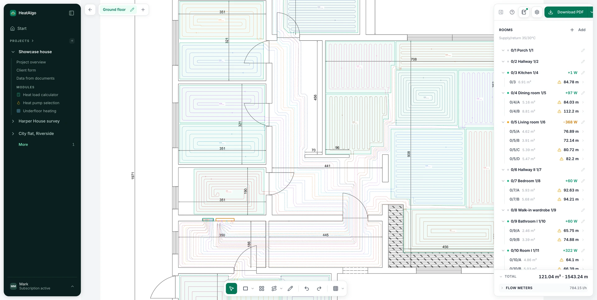
The "Rooms" list shows rooms only. The figure beside each room is the surplus (green) or the shortfall (orange) in Btu/h on an imperial account - it shows which rooms need work. Hovering over a row highlights the room on the plan.
Above the list is one notice strip. The ‹ 1/3 › arrows step through the notices. Pressing a notice shows the full sentence, an explanation and its fix, and the link beside it takes you to what it is about - an unassigned section, for example.
Click a room to open its screen. At the top are the figures: "Area", "Floor output" and "Demand". Below are the "Loops", and last the "Settings" with the "Name" and "Number" fields. When the floor does not cover the heat loss, the issues header says how much heat is missing, and its spacing link sets the recommended spacing in that room's sections. A loop with issues has a tinted header with fix links for the spacing and for "Split". Every detail screen has a "Show on the plan" button.
A room's "Demand" is its design heat loss - from the heat loss calculation or typed in. The floor is sized on that whole heat loss (EN 1264-3, 4.1.3.2, Formula (5)). Heat lost downward through the floor is not subtracted from it: it enters only the flow, as (Q + Φ_FB). A typed value keeps the room's floor data.
Select a section and check "Loop output", "Demand", "Flow", "Return" and the tubing length. Loop output and demand describe different things: the loop's capacity at the current parameters, and its share of the room's heat loss.
In "Project parameters", read "Required supply" and "Design spread". A loop's flow follows EN 1264-3: G = 0.86 · (Q + Φ_FB) · (1 + Ro/Ru) / σ, in the standard's own metric units, where Q is the output to the room and Φ_FB the loop's share of the loss through the floor. The app does the conversion for you and shows the flow in gpm on an imperial account.
The "Flow meters" link at the foot of the panel opens a window with the story's totals at the top and the loops grouped by room, with a subtotal for each room. For each loop it lists the heat the water carries (EN 1264-3, Formula (13)), the temperature spread and the flow - the flow is that heat divided by the spread, on every row. Check the flows and which loop goes to which port there. After you change any parameter, check every room again.
9. Adjust the spacing and split long loops
Recommendations for the whole story appear beside the story tabs, at the top left of the canvas - only when there is something to fix. Two at once fold behind one "2 recommendations" button.
"Apply the recommended spacing" appears when a section's tubing is spaced wider than its room needs. The recommended spacing is the widest of 7.9", 6.9", 5.9", 4.9" and 3.9" (200, 175, 150, 125 and 100 mm) at which the floor covers the heat loss. The action only tightens the tubing and leaves hand-drawn loops alone. Open the preview and check whether the change would make any loop too long. For one room, use the spacing link on its screen; for one section, its settings.
The long-loops recommendation ("Split N long loops") appears when the story has loops over the recommended length for which the app has found cut lines. Its window shows how many sections it will split and which cannot be split.
Use "Split" to divide one section whose loop is too long. The arrow beside it opens "Choose the split": hover over the grid to preview the number of loops, the expected lengths and the warnings. If the automatic split fails, choose another split or adjust the outline by hand.
After splitting, check the new sections' room assignments, supply routes, balance, flows and the manifold's port count. Shorter loops still need to cover the room's heat loss.
10. Download the report and the floor plan PDFs
"Download PDF" creates the project report with results and schedules. Its tables cover every story in the project; the plan it includes shows the story visible on the canvas. To read the room balances and the loop schedule in the report, see the radiant floor heating design guide.
The PDFs print in metric units today - meters, m², °C and W - on every account, imperial included. The app shows imperial; the documents will follow the account's units later.
To prepare a drawing for printing, open the "More export options" arrow beside "Download PDF" - it opens "Project documents". At "Print plan", click "Set" (or "Change" once a paper is chosen). In the dialog choose "Paper size", "Orientation", "Scale" and "Show grid". Check "Print preview": it shows whether the plan fits on one sheet or spans several. Then click "Download PDF". The paper and scale you chose are remembered in this browser, and "Download everything (ZIP)" downloads the report, the plan and the bill of materials in one file.
The printable plan covers the active story. Switch tabs and repeat the export for another. The title block gives the "Project" (the project name), the "Storey" (only when the project has more than one) and the "Issue date". A story nobody renamed prints under the same name as its tab: "Ground floor", "Basement" or "Floor N". The report, the scaled plan and the bill of materials for the supply house are PDFs; DWG and DXF work only as background uploads.
On a free account, "Download PDF" gives a preview report: one room has full results - the first room you draw a loop in. The note above the "Rooms" list names it. The full report and the scaled plan need the project unlocked or a subscription. You can also buy a report for radiant floor heating alone, for that project. If an export is unavailable, check the message beside that download option.
Handy keyboard shortcuts
| Shortcut | Action |
|---|---|
| V | Select elements |
| H | Move a section or manifold |
| C | Calibrate before the scale is set |
| P | Draw a section |
| M | Place a manifold |
| R | Draw a supply route |
| O | Draw tubing by hand |
| G | Toggle the grid |
| Space + drag | Pan the view |
| Esc | Exit the drawing tool |
Find the full list under ? → "Keyboard shortcuts & gestures". For help with drawings and results, see the radiant floor heating FAQ.
Create a free account
A HeatAlgo report follows EN 12831-1 and EN 1264, not ACCA Manual J, and is not accepted for permits or rebates.