
A useful water-based underfloor heating design connects three things: what each room needs, how the proposed floor will provide it, and where the pipes will go. The drawings and calculations should describe the same version of your home, with enough detail for your installer to review the proposed system.
When comparing offers, ask for the drawing, the supporting calculations and a clear account of who checks and installs what. A picture of pipe loops is helpful, but you also need to understand the inputs and decisions behind it.
This guide helps you read that information and organise questions for your installer. If you are still gathering floor plans and product details, start with the underfloor heating planning checklist.
Start with the drawing's version and scope
Check that the drawing reflects your intended room layout. An older kitchen plan can make a neat-looking heating drawing difficult to use once an island, doorway or partition moves.
Look for the project name, floor, revision or issue date, room labels and an indication of scale. Ask which dimensions were checked and which were taken from the original drawing. Record anything that is still subject to change.
The drawing should make the planned heated areas and pipe routes understandable. Discuss fixed furniture, sanitary fittings and other constraints with the installer rather than assuming that one exclusion rule applies to every system.
Your first questions can be simple:
- Is this the latest floor plan?
- Which rooms and areas does this design cover?
- Which measurements or layout decisions are still waiting for confirmation?
- Who updates the design if those decisions change?
Ask how the room requirement and floor output were checked
Ask for the heat requirement of each room and the assumptions used to calculate it. Room heat loss is calculated to EN 12831-1, room by room. Then ask how the proposed floor output was assessed against that requirement. Room area alone does not explain those two values.
For pipes laid in a screed, the floor's output comes from the EN 1264-2 thermal characteristic: pipe spacing, the covering's thermal resistance, the screed cover over the pipe and the pipe diameter give the floor's heat transmission coefficient, multiplied by the logarithmic water-to-room temperature difference - with the limit characteristic set by the maximum surface temperature above all of it. That is why a change from one flooring product to another is a reason to revisit the design inputs, even if both products are advertised as suitable for underfloor heating. Timber floors with spreader plates and low-profile boards use other calculation models or the manufacturer's tested outputs.
You do not need to choose a universal pipe spacing or water temperature yourself. Ask where the selected values are documented and who will confirm them for your system. Our flow-temperature guide explains the relationship between temperature, covering and output.
Suppliers' own published processes show the same ordering - the UK supplier Nu-Heat, for instance, calculates room heat losses, then assesses floor output, then prepares the pipe layout. Read it as an illustration of the sequence, not as a source of values for your own property.
Match the loops on the drawing to the report
A loop label gives you a way to connect a line on the drawing with a row in the report. Ask the designer or installer to show you one loop from start to finish, including its route to and from the manifold.
Useful details to locate include the pipe specification, spacing, length and calculated flow - loop flow and temperature spread follow EN 1264-3. If a room uses several loops, check that the drawing and the schedule identify them consistently. Also ask what the quoted length includes; a room-only length and a complete loop length are different quantities.
The pipe-spacing and loop-length guide explains why the route outside the heated room matters. Use your chosen system's requirements when reviewing limits, rather than treating a single number from an online example as universal.
Example: reading a loop schedule
Below is the loop schedule from a HeatAlgo report for Cedar House, a fictional demonstration project. Its values illustrate the report's fields; they are not recommended settings for another property.
| Room | UFH power [W] | Heat load [W] | Balance [W] |
|---|---|---|---|
| Kitchen | 747 | 650 | 97 |
| Living / Dining | 1875 | 1861 | 14 |
| Bedroom | 813 | 694 | 119 |
| Total | 3435 | 3205 | 230 |
The heat load is recorded at room level, and the balance compares the floor output with that requirement. When the rooms are linked to a heat load calculation in HeatAlgo, the report first deducts from the requirement the heat lost through the heated floor itself, because the floor supplies that heat from below. A note under the report's table gives the amount. Cedar House's heat loads were entered directly rather than linked, so nothing is deducted here.
Below are the same rooms broken out loop by loop. Loop outputs add up to the room output. The room's requirement is shared between its loops, not repeated for each: the report's rotameter page splits it in proportion to loop output and uses each share to set that loop's flow.
| Loop | Spacing [mm] | Pipe [m] | Flow [l/min] | UFH power [W] |
|---|---|---|---|---|
| 0/3/A (kitchen) | 100 | 53.8 | 0.7 | 424 |
| 0/3/B (kitchen) | 200 | 30.0 | 0.6 | 323 |
| 0/1/A (living) | 200 | 49.1 | 1.4 | 434 |
| 0/1/B (living) | 200 | 42.5 | 1.4 | 420 |
| 0/1/C (living) | 200 | 56.1 | 1.7 | 518 |
| 0/1/D (living) | 200 | 50.7 | 1.6 | 503 |
| 0/4/A (bedroom) | 150 | 49.7 | 0.7 | 407 |
| 0/4/B (bedroom) | 150 | 51.0 | 0.7 | 406 |
| Total | - | 382.8 | 8.7 | 3435 |
The Kitchen shows it in figures: 424 W from loop 0/3/A and 323 W from loop 0/3/B make up 747 W against a 650 W requirement, giving the 97 W balance. The 650 W is shared, not repeated: the rotameter page gives 369 W to loop 0/3/A and 281 W to loop 0/3/B, which add up to 650 W. These are calculated values in a demonstration report, not measurements from an installed or tested heating system.
Each row suggests a question. On spacing: which inputs led to this value? On pipe length: what routes are included in the reported figure? In this report, Pipe [m] is the whole loop: the pipe in the room plus the flow and return runs to the manifold. On flow: who will review the flow requirement and commission the installed loop? On output: how does this loop contribute to the room's calculated output?
One input in this example gives a more favourable result than the standard's design procedure would. HeatAlgo evaluates the covering chosen for each section at a fixed thermal resistance - tile 0.05, vinyl 0.08, wood 0.12 and carpet 0.15 m²K/W - and Cedar House is tiled. EN 1264-3 (clause 4.1.3.3) assumes 0.10 m²K/W for residential design. The report's methodology page notes that, for tile and vinyl, the required supply temperature and the balance are therefore more favourable than the standard's procedure gives.
Recalculated with HeatAlgo's method at 0.10 m²K/W, the same floor would fall short in all three rooms at a 39 °C flow temperature and would need about 43 °C. Ask which covering resistance your own design assumed.
In the app, two living-room loops, 0/1/C and 0/1/D, each carry an advisory: their flow is above HeatAlgo's 1.5 l/min threshold, and the app suggests splitting each section in two. The demonstration left both advisories open. The PDF does not list advisories, so ask whoever prepared a report whether any were left open, and why.
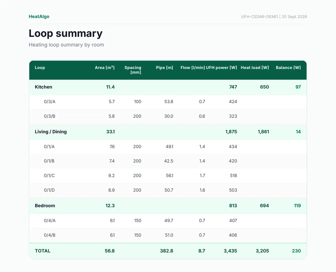
The same schedule as it appears in the PDF report, page 3 of UFH-CEDAR-DEMO.
Check the manifold and controls are part of the conversation
Locate the manifold on the drawing and follow the connecting routes. Ask how someone will access it after cupboards, finishes and other services are in place. If two possible locations are being considered, have the routes checked for each option before deciding.
Ask which rooms you expect to control separately and how those choices relate to the proposed system. Request the applicable control and connection information from the party supplying it. A loop drawing by itself does not establish the full electrical or heat-source connection scope.
Keep a note of the person responsible for each unresolved item. This is especially useful when the heating equipment, floor preparation and finished flooring are supplied by different companies.
Compare what the offers actually include
Copy the worksheet into your notes or print this page, and use the same items for each quote. Write included, excluded or to confirm, then add the supporting document and person in the last column. A blank answer is a question to resolve, not proof that an item has been omitted.
| Item to clarify | Offer A | Offer B | Document and person confirming it |
|---|---|---|---|
| Current floor drawing and revisions | |||
| Room calculations and stated inputs | |||
| Pipe layout, loop labels and schedule | |||
| Floor preparation and build-up: insulation, edge strip, screed, movement joints | |||
| Manifold, connecting routes and access | |||
| Design flow temperature, controls and heat-source connection | |||
| Pressure test before screeding, loop flow settings and commissioning | |||
| Initial heating of the screed, then floor finishing and reinstatement | |||
| Final documents, operating guidance and warranties | |||
| Design changes, responsibility and extra charges |
For example, if Offer A says "pipe layout supplied" and Offer B says "layout and room calculations supplied", those phrases do not establish whether the scopes are equivalent. Ask Offer A where the room calculations are documented, and ask both suppliers who reviews changes to the floor specification. These are fictional wording examples, not comparisons of named suppliers or prices.
Agree how the final installed arrangement and checks will be recorded. Ask the installer which manufacturer instructions apply to testing, commissioning and the initial heating procedure - EN 1264-4 provides for a pressure test before the screed is laid. A planning article cannot set those procedures for your particular installation.
What you can prepare in HeatAlgo
HeatAlgo lets you prepare a water-based underfloor heating layout and associated calculations from your project inputs. It calculates floors with the pipe laid in a screed (type A in EN 1264). For a timber floor with spreader plates or a low-profile overlay board, ask the system manufacturer for its output data instead.
You check the inputs and proposed layout, then can buy the printable plan and PDF report to discuss with your installer. Calculating and drawing are unlimited on a free account, with no card required. Before you buy, the preview shows the building summary and one fully calculated room; the paid report also unlocks the remaining room results and the full loop details for that project. The printable plan shows the project name and scale; write the date on it if you share more than one version.
The software report does not include someone visiting your property, installing the system or signing off the work. Those responsibilities need to be agreed separately for the actual property and selected system.
See how to prepare your plan and reportFor a demonstration of the workflow, watch the manual underfloor heating walkthrough. It uses fictional project data and shows the software workflow, not installation work. For the module itself, read how to use the underfloor heating module.