

The heat recovery ventilation module designs mechanical ventilation with heat recovery for a detached house or a flat and checks it against PN-83/B-03430 with amendment Az3:2000. It calculates every room's air flow, puts supply and extract into one balance and verifies the unit against data from the EPREL register - on the same rooms you described for the heat loss calculation. It is in beta - the badge "Module in beta - preliminary results" is a reminder to treat the results as preliminary. The wizard has six steps: Building, Rooms, Ducts, Unit, Modes, Result. Five of them are forms; the Ducts step is a drawing on the storeys' floor plans. What is new in the module this October: the October 2026 update.
Before you start: the start screen, data from the heat loss calculation and the form
An empty module opens on the start screen "Design heat recovery ventilation with Algo" with the violet "Start with Algo" button and the "I'll fill it in myself" link under it; the "Guide" link in the top-right corner, opposite the back arrow, opens this article in a new tab. "Start with Algo" opens Algo AI: it reads the rooms and their dimensions from the building design and proposes them for the form, and you approve the proposals. When the project has a heat loss result, the screen has three presses with the import first: the violet "Import the heat loss calculation with Algo", the framed "Import without Algo" and the "I'll fill it in myself" link. "Import the heat loss calculation with Algo" brings in the rooms from the heat loss calculation (names, areas, heights, storeys), opens step 1 of the wizard and asks Algo what is still missing for the ventilation design; "Import without Algo" brings in the same data and opens the wizard without Algo. If you open Algo some other way (e.g. from the Algo column) on an empty ventilation module while the project has a ready heat loss calculation, Algo offers the import itself: it says the calculation is ready and puts the "Use the heat loss calculation" press under its answer. A grey line under the buttons names the source and its three figures, e.g. "Heat loss calculation: 7 rooms · 142.5 m² heated · 8.4 kW load". An "Also available" line offers one setting from the client form: the ventilation type and the frost protection. Ventilation only reads from the heat loss calculation - it writes nothing back. The heat loss calculation in turn checks consistency with ventilation: when the project has a designed ventilation system, the heat loss must use mechanical ventilation with heat recovery, the same recovery efficiency and the same room flows; the heat loss module shows discrepancies as remarks. Details in data flows between modules.
The gear on the wizard's bottom bar opens the module settings: in the "Data sources" section you bring the heat loss data in again ("Bring in again") and open Algo (the "Algo AI" row), and "Clear data" wipes the whole module - the start screen then comes back.
Step 1: Building
Three answers: the building kind (a detached house or a flat with its own unit), the number of residents and the unit's frost protection (none, pre-heater, ground heat exchanger, supply throttling). Supply throttling unbalances the system while it runs; the standard allows in a flat with a fireplace, a solid-fuel stove or a gas water heater with gravity flue only natural or balanced ventilation, so in such a flat this strategy is not permitted and the module reports it.
The "Number of residents" is the people living permanently in the whole dwelling, each counted once. It decides the flow of an electric kitchen with a window: up to 3 people 30 m³/h, more than 3 50 m³/h. Left blank, the field takes the total of the rooms' people (shown in grey in the field). Type a number when the rooms count the same people twice - in the bedroom and in the living room, say.
The third group is the intake and the discharge - the WT § 152 questions the module checks for you: where each one is (a wall or the roof), the intake's lower edge at least 2 m above the ground and at least 8 m from a pollution source, a window in the same wall as the discharge (3 m sideways or 2 m vertically), the intake and the discharge in one wall (the intake below or level, at least 1.5 m from the discharge), and on the roof a distance set by the outlet's direction (10 m for a horizontal outlet, 6 m for a vertical one) with the discharge at least 1 m above the intake. You enter the wall intake's height and distance in metres, or tick "Met (at least 2 m) - I will check it on site" (and "Met (at least 8 m) - I will check it on site" for the distance) when you have no site plan. A few conditions are ticks only: a neighbouring building at least 10 m from a wall discharge (8 m if it has no windows), a roof intake at least 0.4 m above the roof and 6 m from sewer vents, a roof discharge at least 3 m from a roof edge with windows below and from windows in the roof or in a wall above it. The report lists ticked conditions as the designer's confirmation, not as a measurement, and an unticked one of those three as a warning to check on site. Every other unanswered question, the intake's height and distance with neither a dimension nor a tick included, blocks the design - nothing is red when you arrive: a blank field is outlined red once you leave it unanswered, press "Next" or open the Result step, and the count on the bottom bar says how many are left.
Step 2: Rooms
The rooms are open sections, one under another. On a phone you see one room at a time: a sticky row at the top shows its name and position (e.g. "2 of 7"), and the room list slides up from the bottom. Every room of the dwelling starts with its kind - tiles at the top: habitable room, kitchen, bathroom, WC, auxiliary room, laundry, stairwell, attic, technical room. The kind decides the system side, the standard's flow and which questions follow; a room added by hand starts as a habitable room, and when the name suggests another kind ("Bathroom", say) a hint with a button appears under the name. Then area and height (enter the volume with sloped ceilings). A habitable room is asked how many people are in that room (20 m³/h each) and the two Az3 conditions that give it a 30 m³/h minimum: more than two doors to the kitchen, bathroom or WC, or a room upstairs - the room stays on supply. Once one is ticked, a line under them gives the room's minimum. The system side (supply, extract, transfer) is proposed from the kind; you can override it. You do not need to type the door undercut: the minimum follows from the room kind - 80 cm² in a habitable room, 200 cm² in a kitchen and a windowless auxiliary room, 220 cm² in a bathroom or WC (WT § 79) - and the report states it for every room with the gap under an 80 cm door. The "Door undercut or grille" field is for an opening that already exists; one smaller than the minimum is an error. A calculator turns the gap and the door width into cm². A kitchen has extra fields: the cooker (gas, coal, electric, induction - the standard gives different flows), kitchen without an external window, open-plan kitchen, hood, and the dwelling's occupants, read-only (from the Building step or the total of the rooms - it decides 30 or 50 m³/h for an electric kitchen with a window). An auxiliary room is asked whether it is windowless. Two fields apply to the whole dwelling: an open gravity ventilation grille (a blocking error - the standard does not allow it beside heat recovery; blank the duct) and a fireplace or gravity-flued appliance.
You do not enter flows - the module computes them from these data. The rules of the standard it checks without a drawing: at least one supply room and one extract room, a windowless kitchen with a gas cooker must have mechanical extract, mechanical and natural ventilation are not combined in one dwelling, a hood is not connected to the heat recovery system, a garage or a boiler room is not connected to the dwelling's system.
When you want a flow of your own - a large living room, say, where 20 m³/h per person gives less than you consider sound - type it in the "Design flow" field. The "?" beside the field gives the minimum by the regulations - below it the design is blocked. The message about a typed value shows under the field. A typed flow is final: the balance spreads the missing difference over the other rooms, and when there is nowhere to put it the report warns and states the difference. On the Result step the same value is edited in the "After balancing" column.
Step 3: Ducts
You draw the duct network on the storeys' floor plans. Preparing a storey has four steps, led by the "Storey setup" panel:
- Upload the storey's plan - PNG, JPG, WEBP or PDF; from a multi-page PDF you pick the page, and the walls read off the drawing snap the points you place. The ventilation plan is stored separately and never overwrites the underfloor heating plan. Everything about the plan sits under the gear in the panel header: upload and replace, adjust (turn, crop the margins, fade the background), scale and position.
- Set the scale (C) - two points a known distance apart and the distance in centimetres. Without a scale only panning works; the scale is per storey.
- Give the storey height - floor to floor of the storey above; the riser lengths are computed from it. In the same place you set the storey zone: heated or unheated (an unheated loft or cellar). The zone decides which ducts need insulating; while a storey has none, the panel says how many ducts are waiting on a storey zone.
- Line the storey up with its neighbour (G) - point at the same building point on both plans, e.g. a stair corner; the plan shifts so the points coincide. There is also a mode for dragging the plan by hand, with Shift to resize it.
Then you draw: "Place a point" (P) places the unit, a terminal, an intake, a discharge, a distribution box, a silencer or a tee, with the system side (supply, extract, intake, discharge) chosen with the arrow next to the tool; "Draw a duct" (R) connects two points with bends along the way; "Draw a riser" (E) connects two storeys - the first click on this one, then you switch storey and click the other end; "Select and edit" (V) opens the panel of a point or a duct. A tee is a branch on the duct itself, with no box - a spiral-duct system needs no distributors; like a box it needs the coefficient Z from the tee's datasheet. The grid (S) with its spacing and anchor keeps ducts straight; Shift locks the angle to 90°, Shift+Alt to 45°.
A new terminal has "With plenum box" on: the terminal and its box are one element with one mark (the terminal's circle in a square), with no run between them. The resistance field in its panel is "Set coefficient Z" - the whole set's loss from the manufacturer's datasheet - and the order form lists the box by its spigots. New drawings no longer get a separate plenum box. A box from an earlier drawing that sits within 0.5 m of a terminal shows "Merge into a set" in its panel.
With "Select and edit" (V) you correct what is drawn: drag a point or a bend of a duct - it lines up with the neighbouring points (pink lines), Shift keeps one axis, Ctrl turns snapping off, and the leg lengths show as you drag; double-click the selected duct to add a bend, double-click a bend or press Delete to remove it. An intake or a discharge turns by its handle (15° steps, 90° with Shift) or with the O key, and the point's panel has "Direction": "Automatic" or "Own angle" - the mark no longer turns by itself when the duct's route changes. Ctrl+Z undoes, Ctrl+Shift+Z redoes.
The drawing speaks the language of installation drawings: every point has a mark (U1 the unit, S1/E1 a supply and an extract terminal, DS1/DE1 a distribution box, PS1/PE1 a plenum box, AS1/AE1 a silencer, T1 a tee, IN1 the intake, EX1 the discharge), every run a number R1, R2... written into the duct, and from a working zoom the flow, the diameter and the length under it. Arrows on the ducts show the direction of flow, a damper has its own symbol. The labels switch on the toolbar shows everything, the marks only, or nothing; the legend of the symbols sits under the storey bar. Beside the labels switch, "Ducts to scale" draws the runs at their nominal diameter when the storey has a scale, and a flexible run as one parallel line per pipe. A run stays light while its size is the automatic proposal and turns solid once you choose it.
You assign a terminal to a room from the list ("Pick a room"), not by its position on the plan - without an assignment its flow is not computed. The duct panel starts with the "Duct type": spiral, EPP or flexible. A run from the distribution box to a plenum box or a terminal starts as flexible, the rest as spiral. The diameter is proposed from the sizes wholesalers stock (spiral 100-500 mm, EPP 125, 160 and 200 mm) - not from any number. 63 and 80 mm ducts are not proposed, because wholesalers do not stock them; a diameter you type stays as you typed it. A flexible duct is several Ø75 or Ø90 pipes side by side between the distribution box and the plenum box: the module proposes how many (for example 2 × Ø75 for 40 m³/h, 2.5 m/s in each pipe), and you can type your own number. The flexible pipe's resistance comes from the manufacturer's datasheet: the pressure drop in Pa/m at a flow through one pipe, one value for every Ø75 pipe in the project (and another for Ø90); without it the system's resistances are not computed. The panel also shows the length from the drawing (you can enter your own), elbows, flow, the diameter proposal (which can be overridden), and insulation (automatic from the storey zone: heated or unheated, with a manual override). Every bend in a run is priced at the angle it is drawn at (PN-76/M-34034, Table I-4, R/d 1.0); a point on a straight line, turning less than 5°, is no bend. On a flexible run the panel shows "Bends" instead of "Elbows", and the order form orders no elbows for it. The panel of a box, a silencer, a tee and an intake has the "Coefficient Z" field - the local loss copied from the manufacturer's datasheet, with a button to enter it into every point of that kind; without it the system's resistances are not computed (an intake and a discharge without a value count as sharp-edged, Z = 1.0). Fittings saved in My library (with the ζ coefficient from the datasheet) you pick with the book icon beside that field. In the duct panel you switch on a balancing damper and give its coefficient - a damper without one also holds the resistances back, since a zero loss would understate them.
The storey-alignment findings say plainly what to fix: "This storey's plan and the one next to it overlap by only X %" - check this storey's offset and scale; "This storey's scale differs from the one next to it by a factor of N" - the reference distance was measured on a different drawing; "This riser's ends are X m apart in plan" - check how the storeys line up, or draw a horizontal run; "This riser crosses a storey with no height set" - give every storey on the riser's path a height.
Network rules: one unit on the drawing, ducts form a tree with no loops, supply and extract meet only at the unit, the intake and the discharge must be connected (without them the resistances come out too low), every point must have a path to the unit. A breach does not stop the report: the report is produced with the "Incomplete design" stamp, the duct plan still downloads, and the faulty points glow red on the drawing. Drawing needs a larger screen; the other wizard steps work on a phone.
Step 4: Unit
Two routes: "EPREL register" - you pick manufacturers (several at once) and the app fetches units from the European register with declared data (maximum and reference flow, recovery efficiency, fan power, sound power, energy class) and shows which will deliver the required flow; filters narrow by efficiency, power and noise. Or "From the DTR" - you copy the data from the documentation; such data is marked as not verified in the register. The register does not publish the fan curve, so in both cases you enter it from the datasheet: at least three points of flow and pressure, because a straight line between two points overstates the available pressure.
A unit you use in many projects you save in My library together with the fan curve from the datasheet. On this step you pick it with the book icon beside the model field, and the pick copies its data into the project. How the library and its limit work is in the heat loss calculation guide.
The unit verdict: whether it delivers the required flow, whether the operating point lies below the reference flow, and the pressure - a margin or a shortfall in pascals once the system's resistances are computed. The "Pressure reserve [%]" field adds a margin to the required pressure for dirty filters and the uncertainty of the resistances; it is your design assumption, not a requirement of the standard, and the report labels it so.
Step 5: Modes
You describe how the system works away from the design point: the nominal, reduced and boost modes, with the flow as a percentage of the design flow or in m³/h. "Add the three basic modes" creates the set. The standard allows reducing the flow only at night and at most to 60% of the value required for each room separately; a reduction in the daytime is not permitted. For the kitchen the standard recommends the option of a periodic increase in extract. Fewer than three modes is a remark, not a block. A boost mode with a flow above the unit's maximum, or off its fan curve, is rated "Not permitted" - a unit at 99 % of its flow at nominal has nowhere to take a boost from.
Step 6: Result
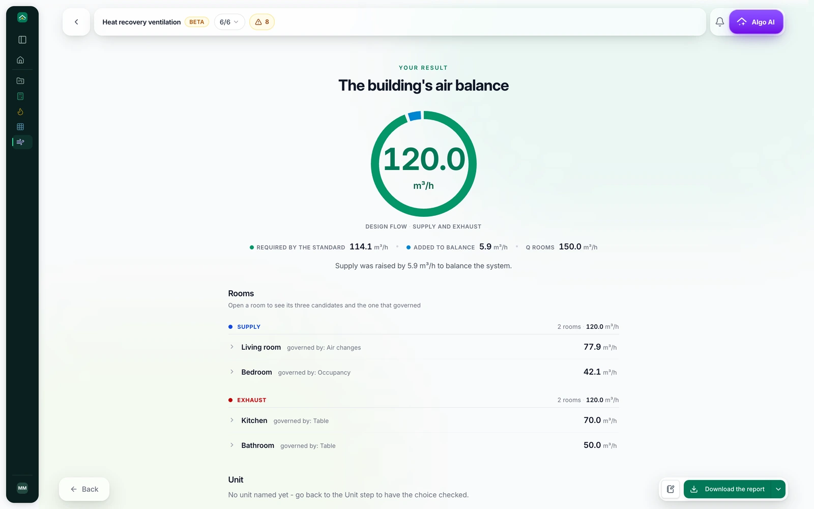
The building's air balance: supply and extract, marking how much the standard requires and how much was added for balance. The room list with role, flow and the criterion that decided (table, people, air change rate) - a click shows the three candidates, and the "After balancing" column lets you correct the proposal by hand and return to it with one click. Remarks with error and warning codes and the "Go to step" and "Show on the drawing" buttons. "Unit requirements" before the unit section: the design flow, the required available pressure for supply and extract separately with the governing side, the reserve, the reduced and boost mode flows, the declared unit's sound power - the unit is then a verification of those requirements. The unit section with the flow and pressure verdict, the catalogue efficiency and the efficiency assumed in the heat loss calculation. "System resistances" - both sides' losses and the two critical routes listed run by run with each run's loss, the intake and the discharge as a separate part of the route. "Commissioning card" - the setting of every terminal, the damper on its duct, and an empty "Measured" column to fill in with an anemometer after installation. "Bill of materials" - generic types and quantities: spiral, EPP and flexible ducts in metres by diameter (a flexible duct counted as the number of pipes times the run length), insulation, terminals, plenum boxes by spigot count (e.g. 2 × Ø75), distribution boxes, silencers, intake, discharge, elbows, tees, reducers (e.g. Ø200/Ø160 where the diameter changes at a riser or a tee), dampers. In the report, the "Requirements for the build" page gives each room's door undercut and the intake and discharge conditions the designer confirmed. You download the report and the to-scale duct plan from the bottom bar: on the Result step square icon buttons take the place of "Next" - report notes and the download button (a download icon with a small arrow), which opens a menu with "PDF report" and "Duct layout". Before the result is ready, the button is grey and the menu's rows say "Available once the result is ready". Both files have the same symbols and legend as the drawing on screen. The duct plan's title block gives the project, the storey and "Issue date", and the storeys carry the same names as the tabs on the drawing (e.g. "Ground floor", "Floor 1"); the client view keeps the flows and hides the marks - see the article on reports. The buttons are grey until there is a result. Until then the step shows a sample result under frosted glass, and in the middle what is missing - for example rooms without dimensions, with a "Fill in" button; when the calculation fails on our side, a "Try again" button.
What the module does not do
It does not do acoustics: silencer selection from octave-band data and room noise levels are a separate piece of work. It has no manufacturer catalogue: diameters are proposed from the series sold on the market, the flexible duct's resistance comes from the datasheet you type in, and rigid ducts' resistances from generic coefficients. The duct editor is a design tool that counts what has to be bought - not an installation drawing with the symbols of particular terminals and boxes.
Free account
On a free account you see the roles, required flows, balance, duct velocities and the design flow from the unit requirements. The resistances, required pressure, critical routes, unit verdict, commissioning card and printable duct plan are unlocked by a report, which covers the whole project - see what is free and what a report unlocks. You can also buy a report for heat recovery ventilation alone, for that project.